Global ELF/VLF Wave Propagation
ELF/VLF (3 Hz - 30 kHz) waves can propagate to large distances around the globe with low attenuation rates (~1 dB/Mm) within the waveguide formed by the Earth and the lower ionosphere. One natural source of ELF/VLF waves is the lightning electromagnetic pulse (EMP), which is produced during a lightning return stroke. Our research group performs measurements of the ELF/VLF lightning impulse (radio atmospheric, or sferic) at large distances from the lightning flash in order to improve long-distance wave propagation models, to characterize the globally-averaged electron density profile, and to quantify Earth-ionosphere waveguide excitation.
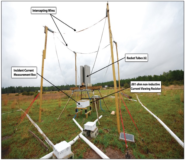
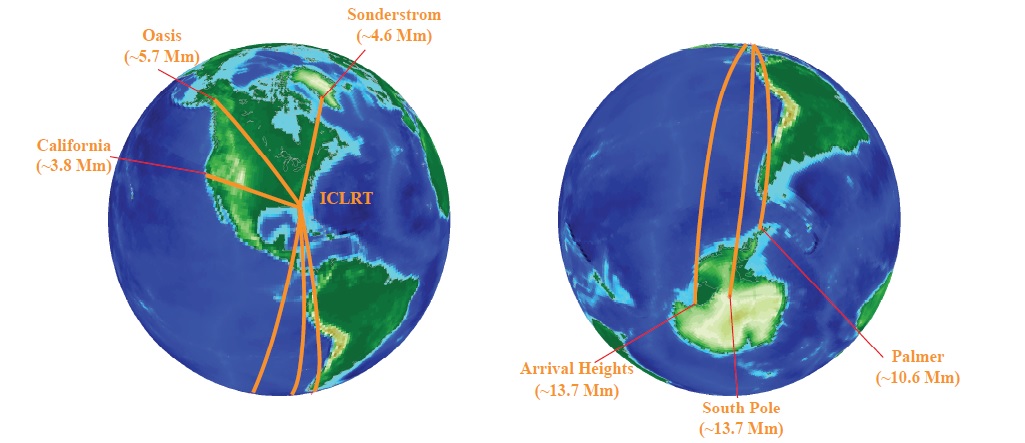
While our research group performs measurements of ELF/VLF sferics produced by natural lightning, we focus on measurements of sferics associated with rocket-triggered lightning. Lightning produced by rocket-and-wire triggering experiments at the International Center for Lightning Research and Testing (ICLRT) at Camp Blanding, Florida provide a known lightning location as well as a multitude of high resolution lightning measurements (see Figure 1). We compare the measured lightning source characteristics with ELF/VLF observations performed around the globe (see Figure 2).
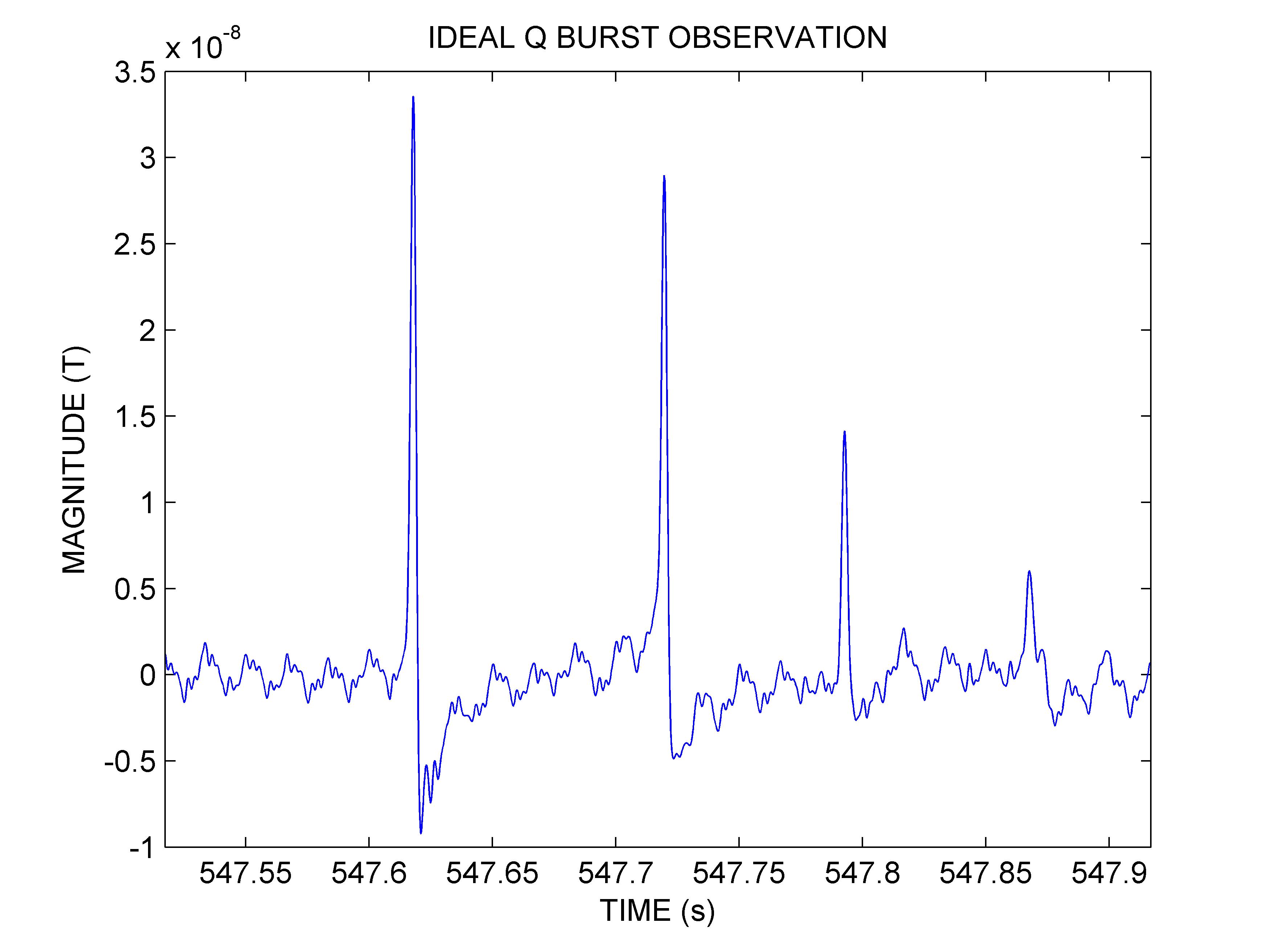
As an example, we present experimental observations of a natural lightning flash as observed at Arrival Heights, Antarctica in Figure 3. This particular ELF sferic is produced by a single lightning return stroke, although it has four clearly discernible components (separated in time). In this case, the first impulse results from the shortest path from the lightning flash to the receiver (i.e., the great-circle-path); the second pulse results from the signal propagating the opposite direction around the globe (i.e., the antipodal path); the third pulse is the same as the first pulse, plus one around-the-world (ATW) path delay; and the fourth pulse is the same as the second pulse, plus one ATW delay. In Figure 3, we can easily identify peak from the great-circle-path, the peak from the antipodal path, the peak from the "direct" ATW path, and the peak from the "antipodal" ATW path.